Revision Notes
Cambridge O Level Physics: Electricity and magnetism (5054) – Revision Notes
Condensed revision notes for Electricity and magnetism in Cambridge O Level Physics 5054: formulas, definitions, safety rules, a self-test and slips.
- Subject
- Physics
- Level
- O LEVELS
- Topic
- Electricity and magnetism
- Author
- Marlbridge Academic Team
- Updated
- Reviewed by
- Hassan (what this means)
Aligned to Cambridge O Level Physics (5054), 2026-2028. Official specification .
Syllabus page (what it covers and how it is assessed): Cambridge O Level Physics.
Syllabus points this page covers
5054
- 4.1 Simple magnetism and magnetic fields
- 4.2 Electrical quantities
- 4.3 Electric circuits
- 4.4 Practical electricity
- 4.5 Electromagnetic effects
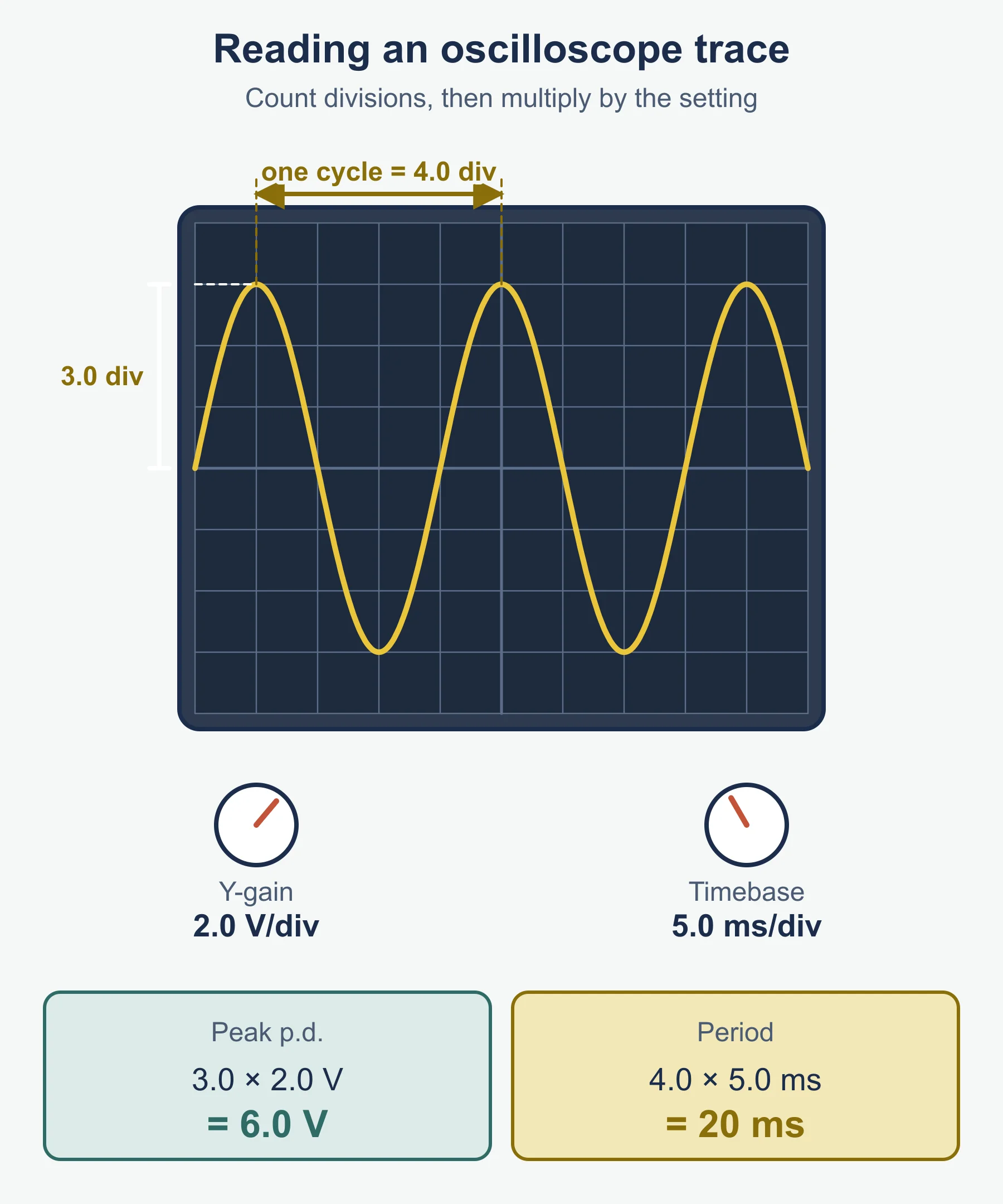
- 4.6 Uses of an oscilloscope
Found an error? Report a correction.
Need help with this topic? Request a free trial class for O Level Physics (5054).
These notes condense Section 4, Electricity and magnetism (4.1 to 4.6), of the Cambridge O Level Physics 5054 syllabus for examination in 2026, 2027 and 2028. For full explanations and worked examples, read the study guide. Test yourself with the practice questions, tick off topics on the checklist, find weak spots with the free diagnostics and return to the course hub.
Equations to recall
| Quantity | Equation | Unit |
|---|---|---|
| Current | I = Q/t | amp (A) = C/s |
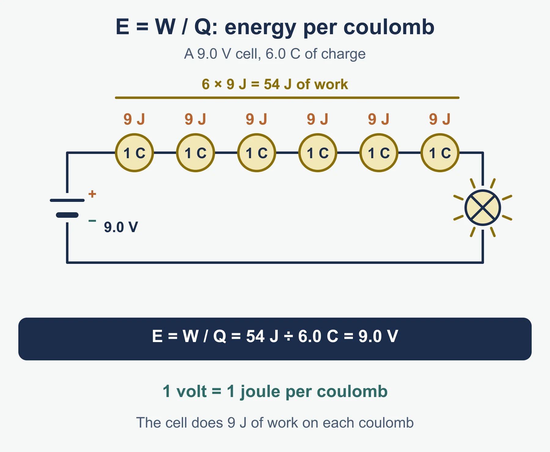
| E.m.f. | E = W/Q | volt (V) = J/C |
| P.d. | V = W/Q | volt (V) = J/C |
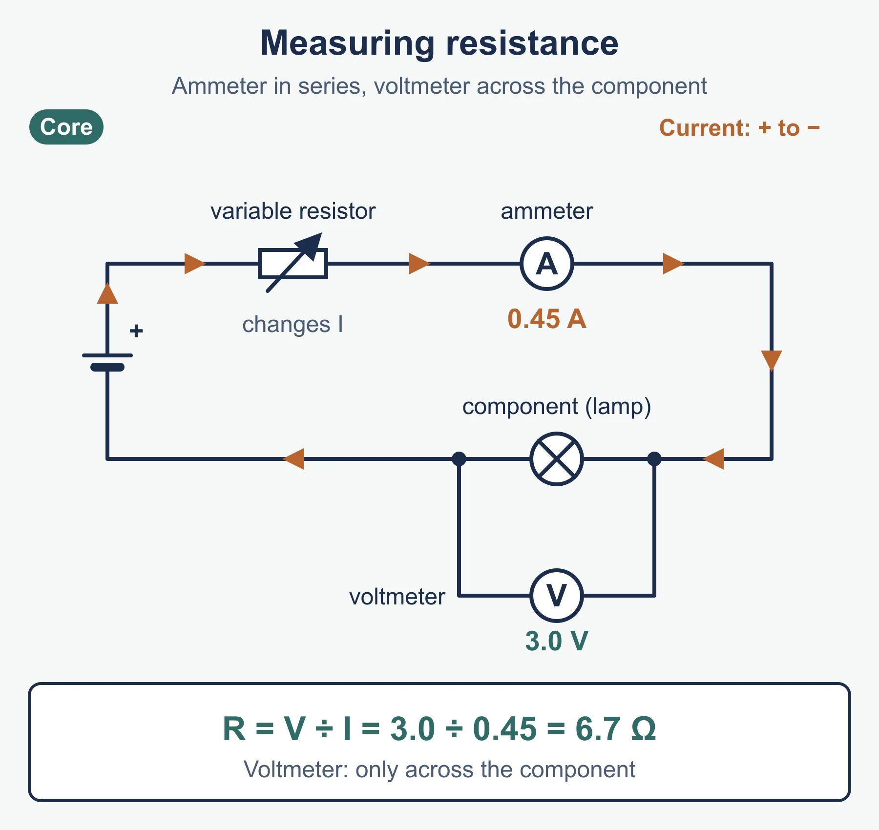
| Resistance | R = V/I | ohm (Ω) |
| Series resistors | R = R1 + R2 + … | Ω |
| Two parallel resistors | R = (R1 × R2) ÷ (R1 + R2) | Ω |
| Potential divider | R1 ÷ R2 = V1 ÷ V2 | |
| Power | P = IV | watt (W) |
| Energy | E = IVt | joule (J) |
| Cost | kW h × price per kW h | |
| Transformer | Vp ÷ Vs = Np ÷ Ns |
Convert before you substitute: kW to W for P = IV, minutes to seconds for E = IVt, but keep hours for kW h.
4.1 Magnetism
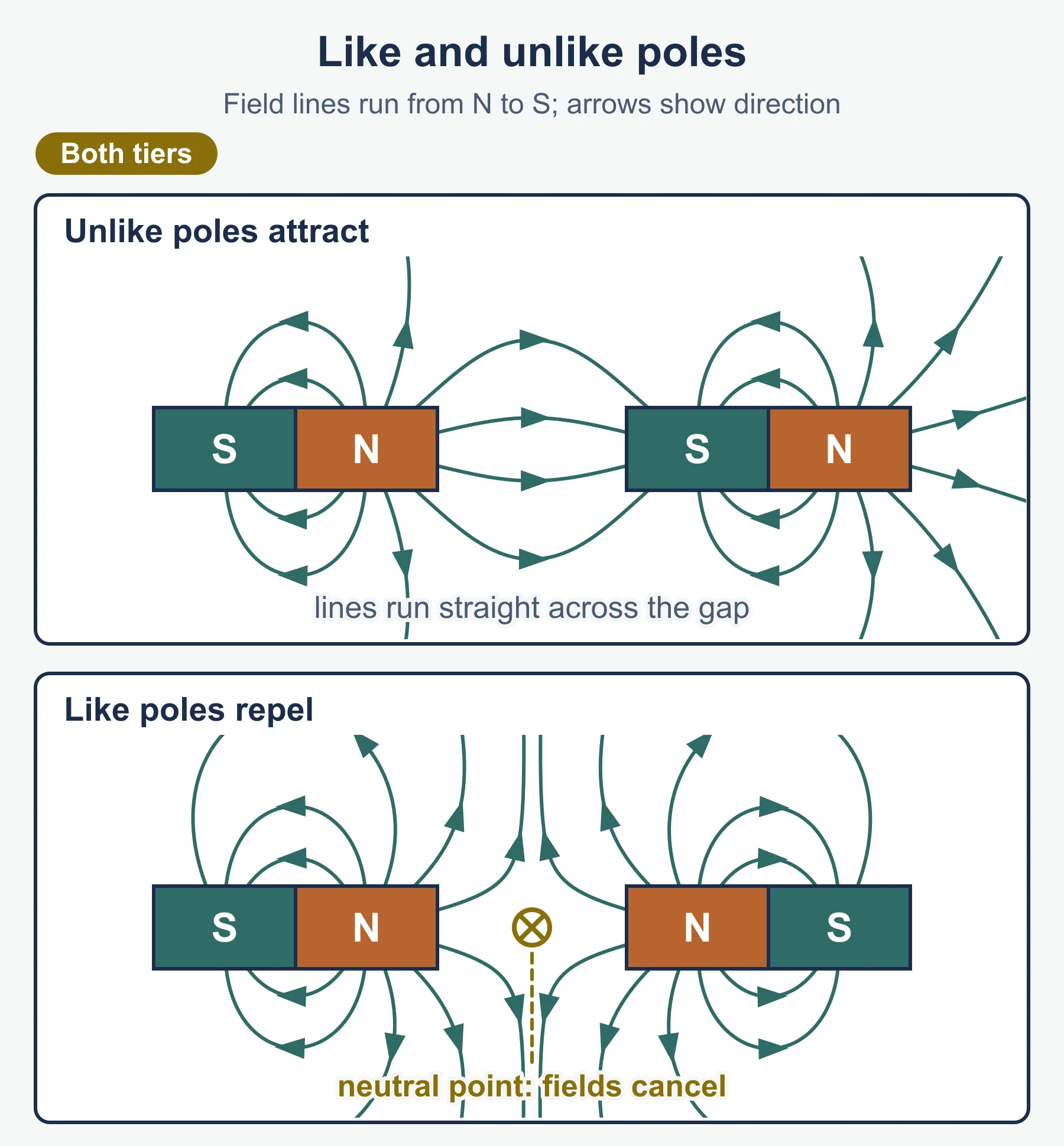
- Like poles repel; unlike poles attract. Only repulsion proves that an object is a magnet.
- Magnetic: iron, steel, cobalt, nickel. Not magnetic: copper, aluminium, plastic.
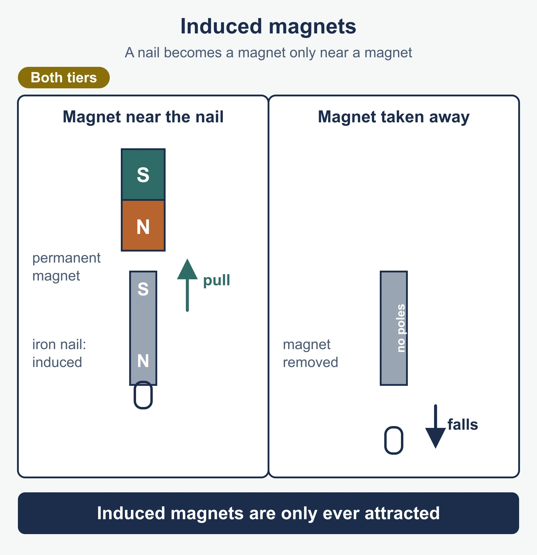
- Induced magnetism: the end of a magnetic material nearest an N pole becomes an S pole.
- Temporary magnet: soft iron, easy to magnetise and demagnetise. Permanent magnet: steel, keeps its magnetism.
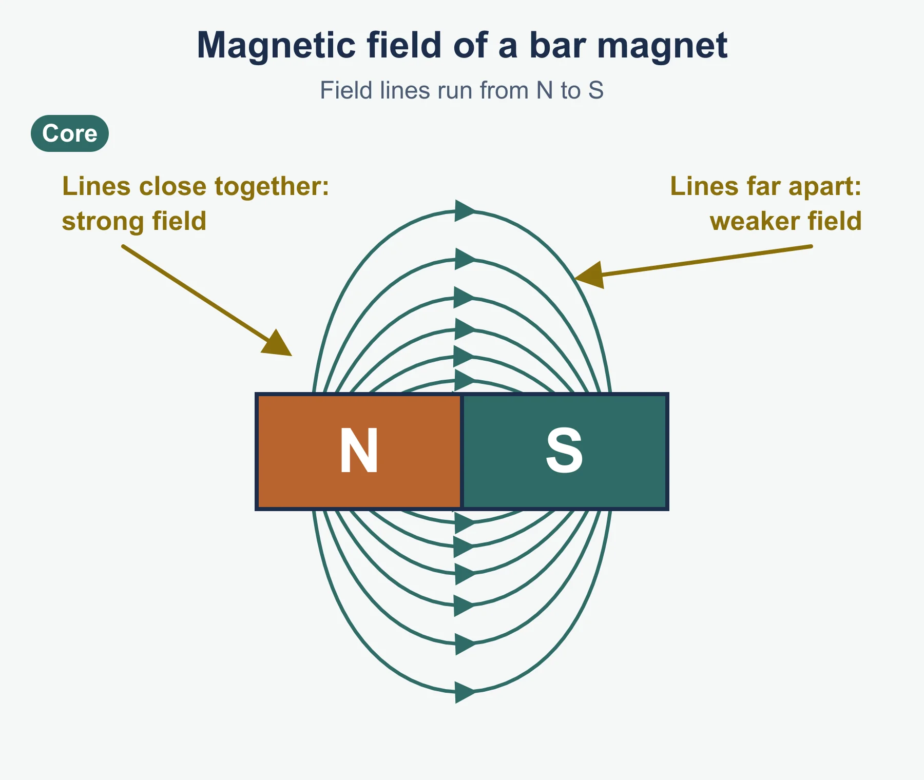
- Field: a region where a magnetic pole feels a force. Direction = force on an N pole. Outside the magnet, lines run N to S, never cross, and bunch up where the field is stronger.
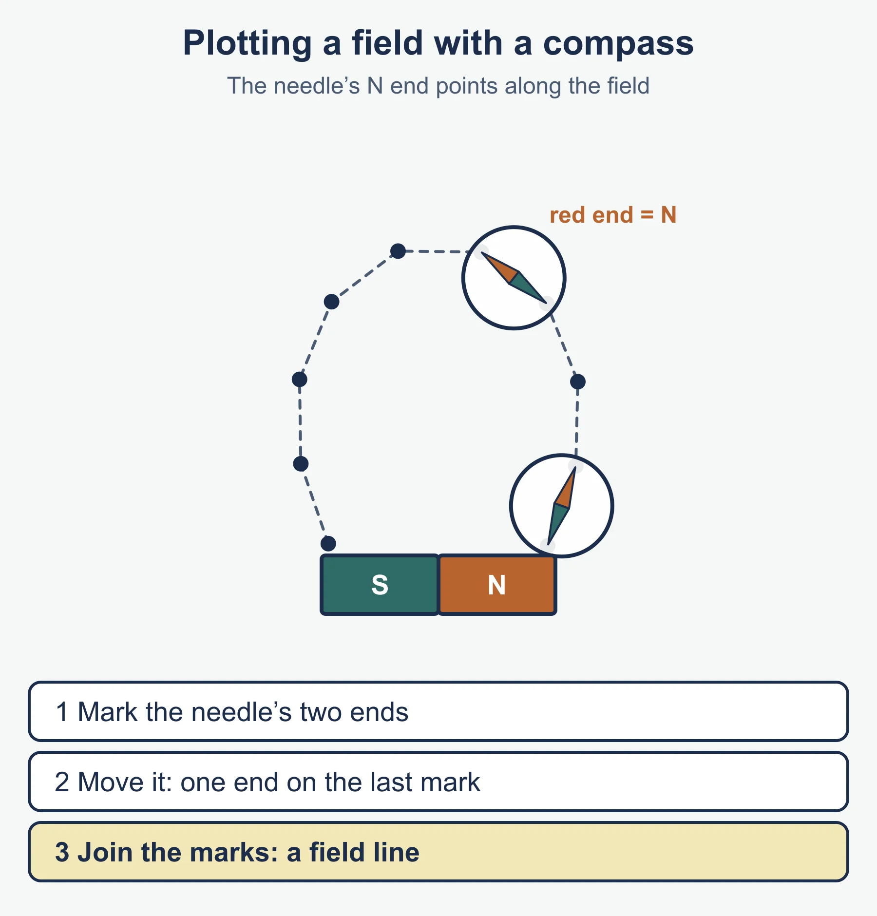
- Plotting: place a plotting compass, mark both ends of the needle, move it along, repeat, join the dots. The needle’s N end shows the field direction; iron filings show the pattern.
- Uses: permanent magnets in compasses; electromagnets in cranes and relays, where the field must switch on and off.
4.2 Charge, current, e.m.f., p.d., resistance
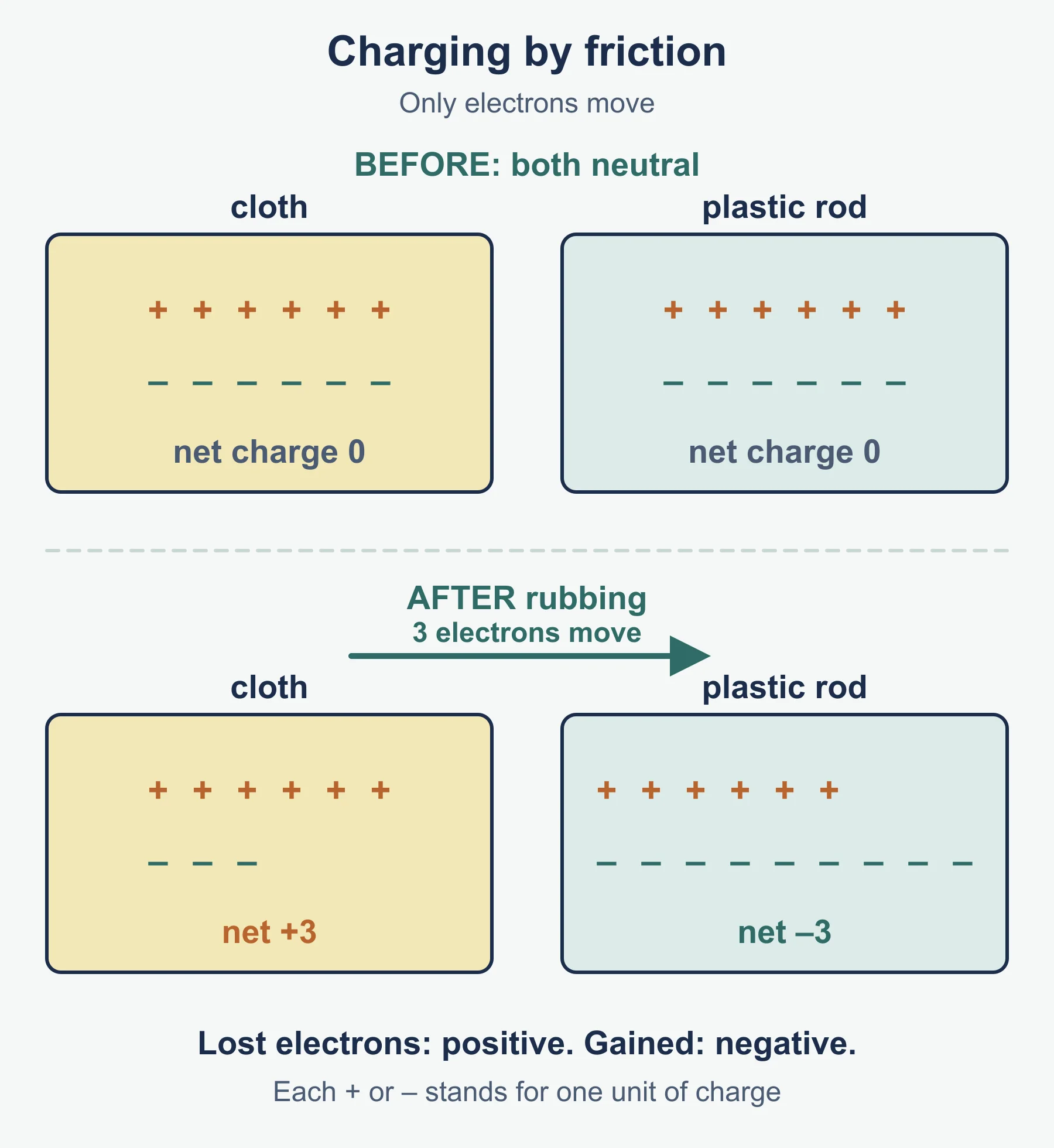
Charge. Measured in coulombs. Friction moves electrons only: the gainer is negative and the loser is positive. Like charges repel; unlike attract.
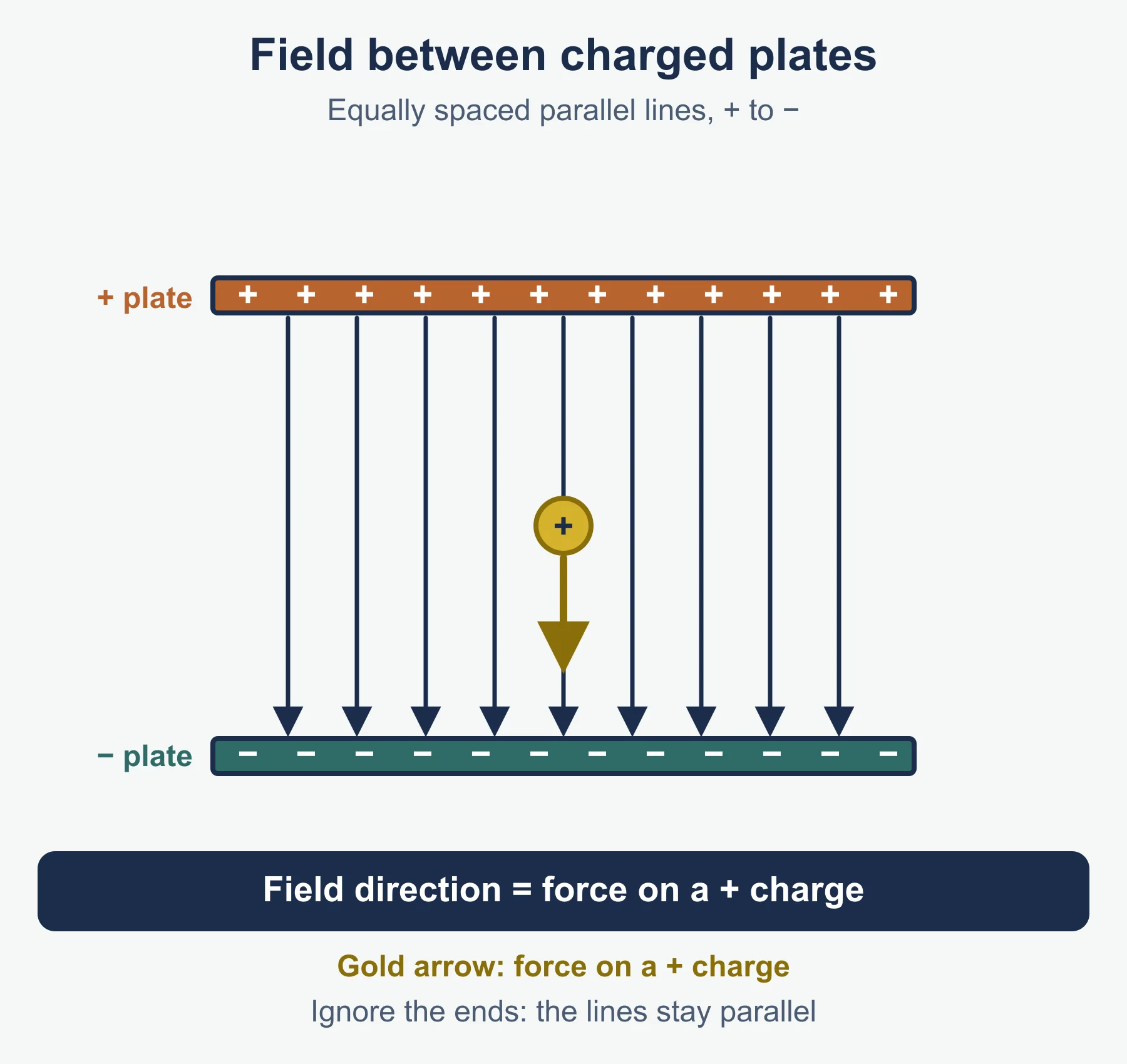
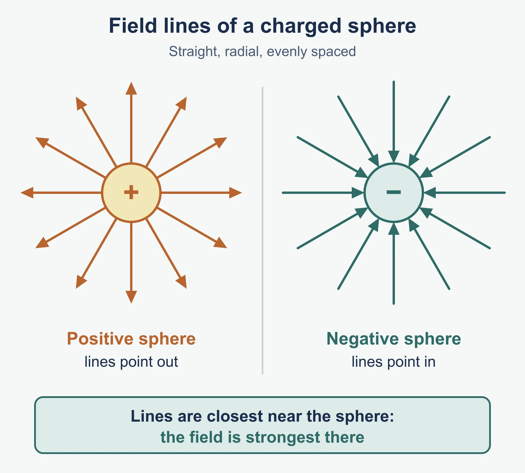
Electric field lines point the way a positive charge would be pushed.
| Source of field | Pattern |
|---|---|
| Point charge | Radial: out for positive, in for negative |
| Charged conducting sphere | Radial, as for a point charge |
| Oppositely charged plates | Equally spaced parallel lines, positive to negative |
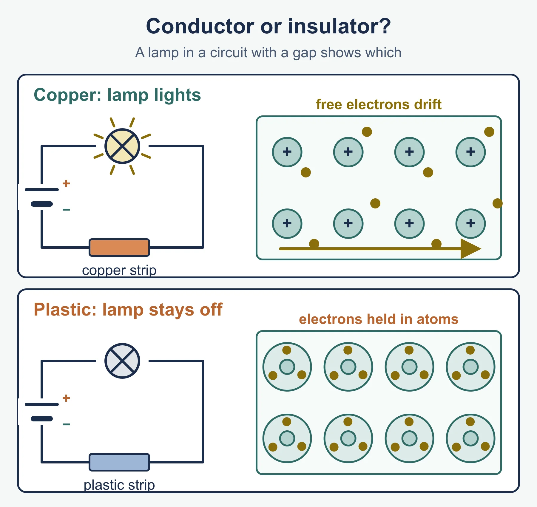
Conductors and insulators. Conductors (metals, graphite) have free electrons. Insulators (plastic, glass, rubber) hold their electrons in atoms. Test with a lamp in a gap in a simple circuit.
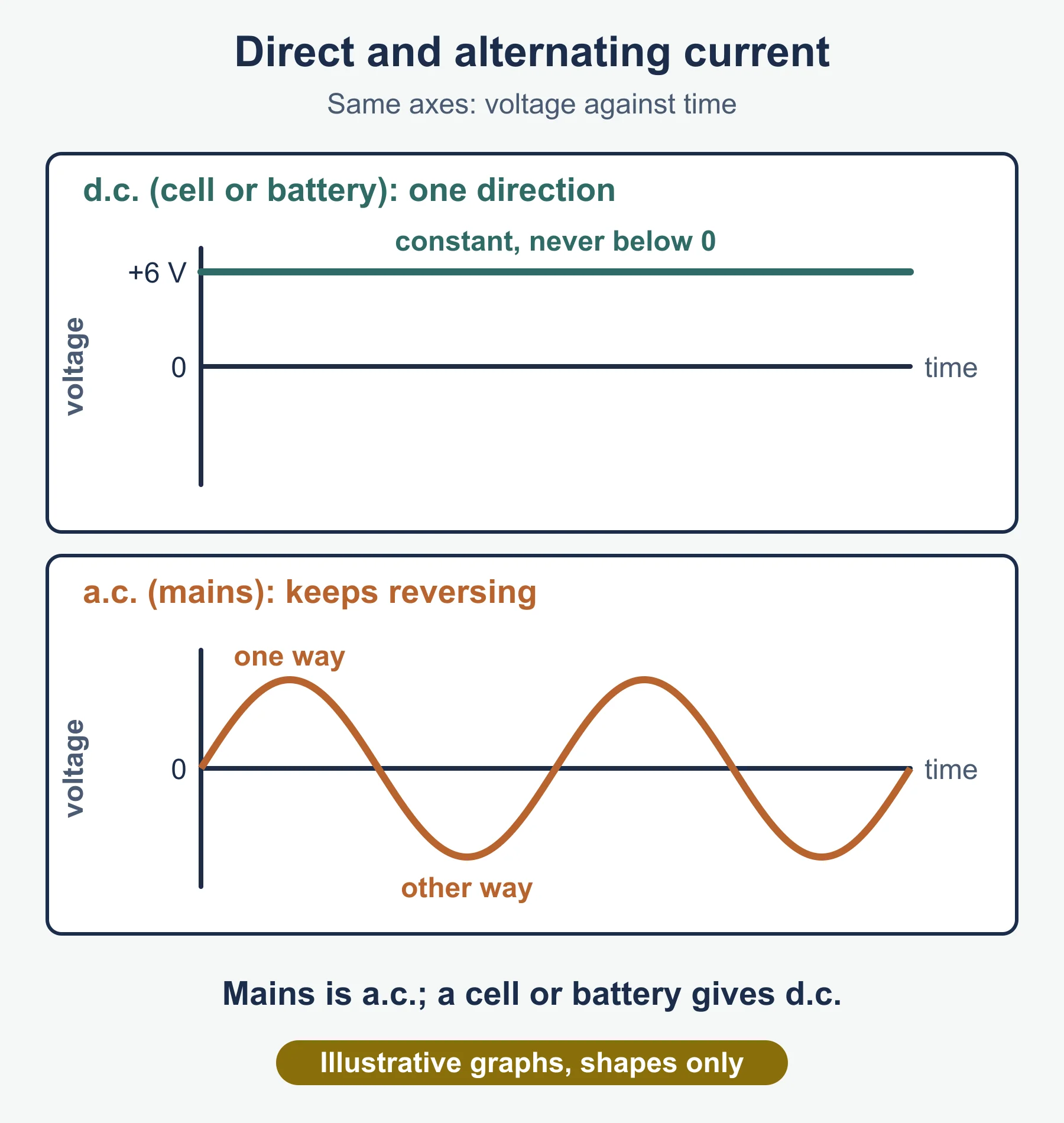
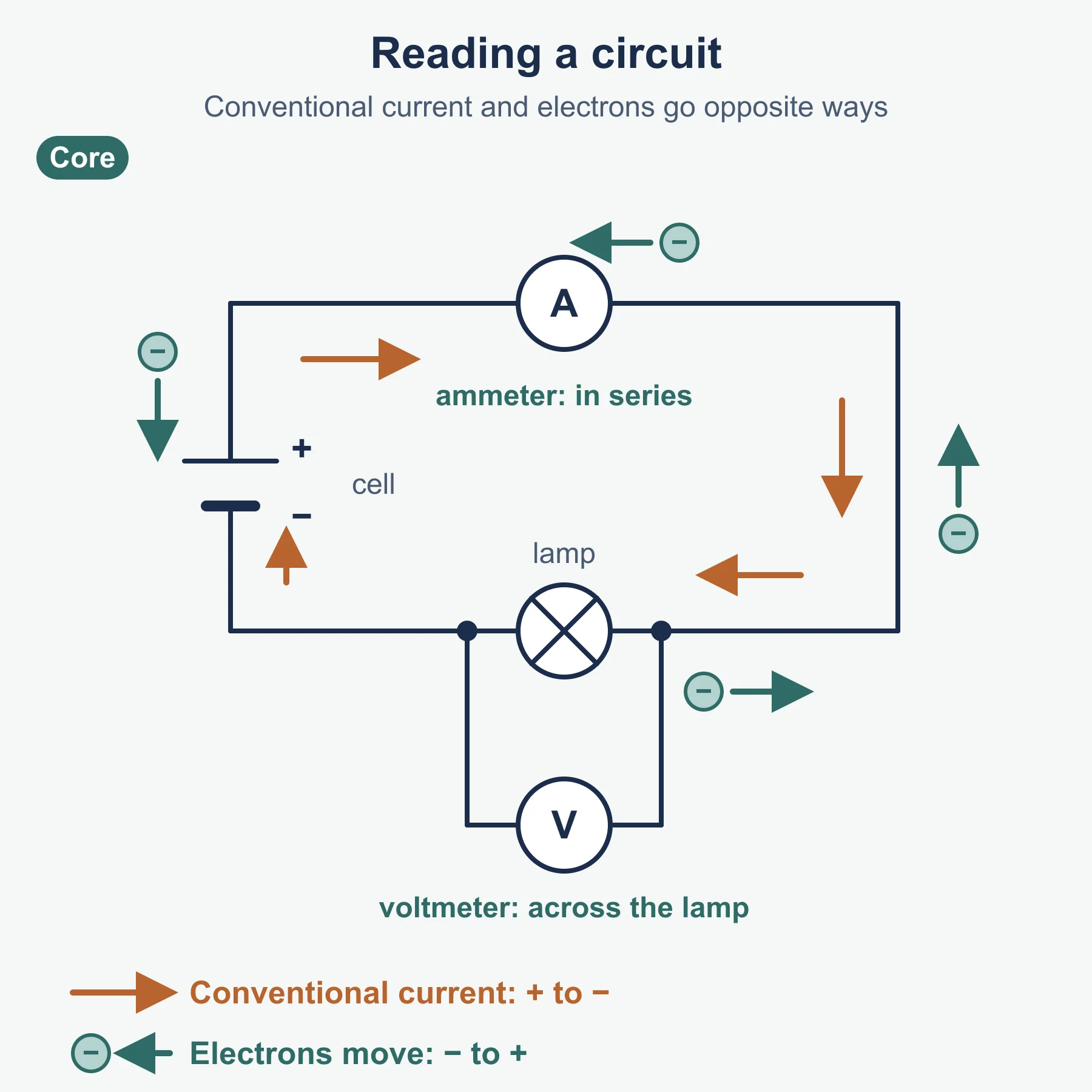
Current. Conventional current runs positive to negative; free electrons drift negative to positive. D.c. flows one way; a.c. reverses. Ammeter in series, voltmeter in parallel. Choose a range above the expected reading.
E.m.f. versus p.d.
| E.m.f. | P.d. |
|---|---|
| Work done by a source per unit charge | Work done by unit charge passing through a component |
| Energy given to charge, round the whole circuit | Energy taken from charge, across one component |
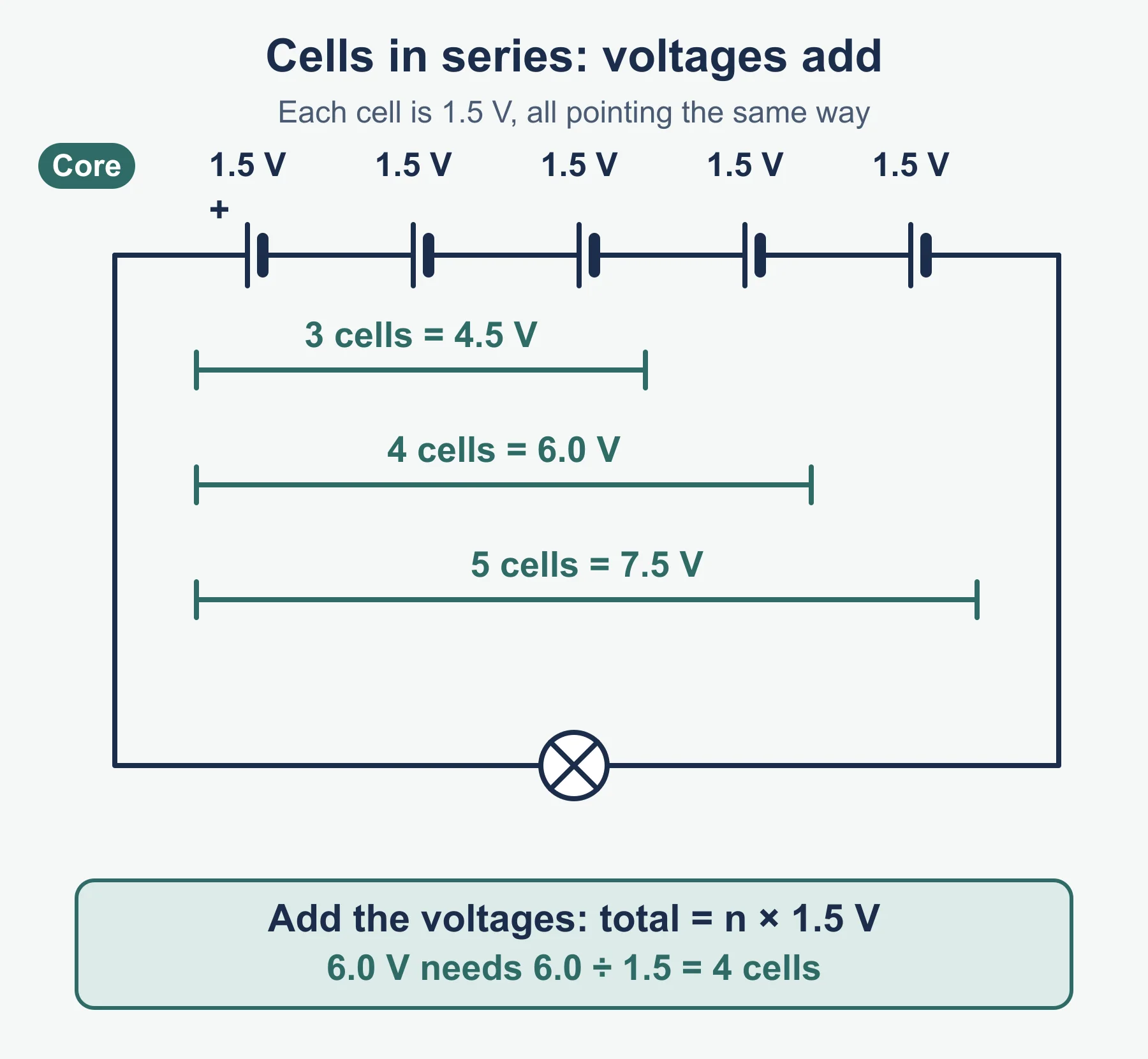
| Cells in series add; identical cells in parallel give one cell’s e.m.f. | Series p.d.s add to the supply p.d. |
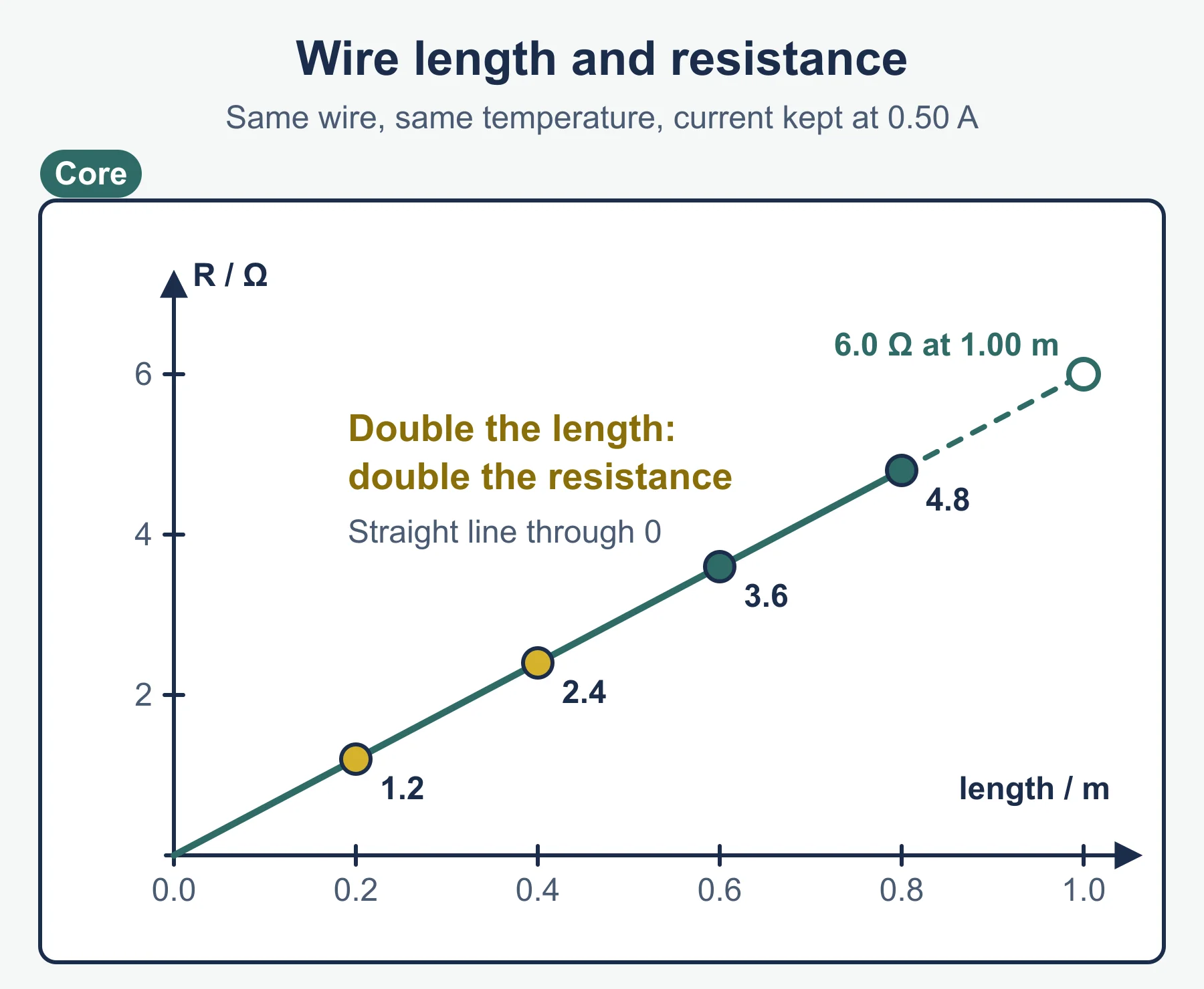
Resistance and wires. R grows in direct proportion to length and falls in inverse proportion to cross-sectional area. Twice the length means twice R; twice the area means half R.
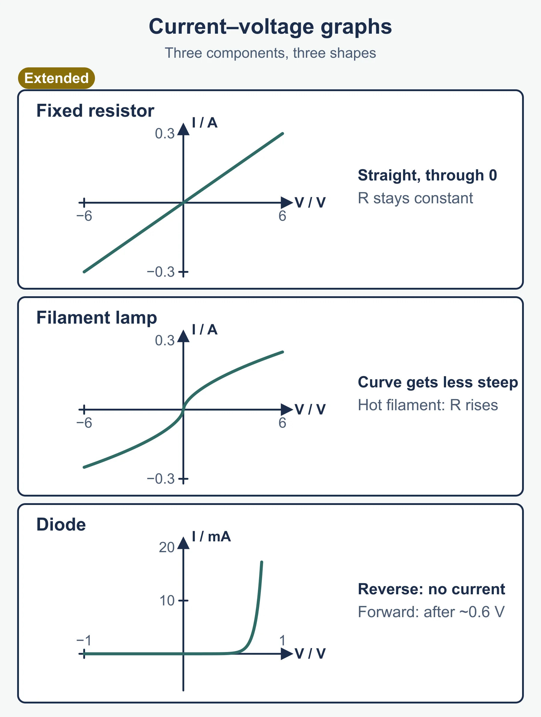
Ohm’s law. Current is proportional to p.d. while the temperature stays fixed.
| Component | I-V graph | Reason |
|---|---|---|
| Fixed resistor | Straight line through origin | Constant R |
| Filament lamp | Curve, flattening | Hot filament has higher R |
| Diode | Near zero one way, steep rise the other | One-way conduction |
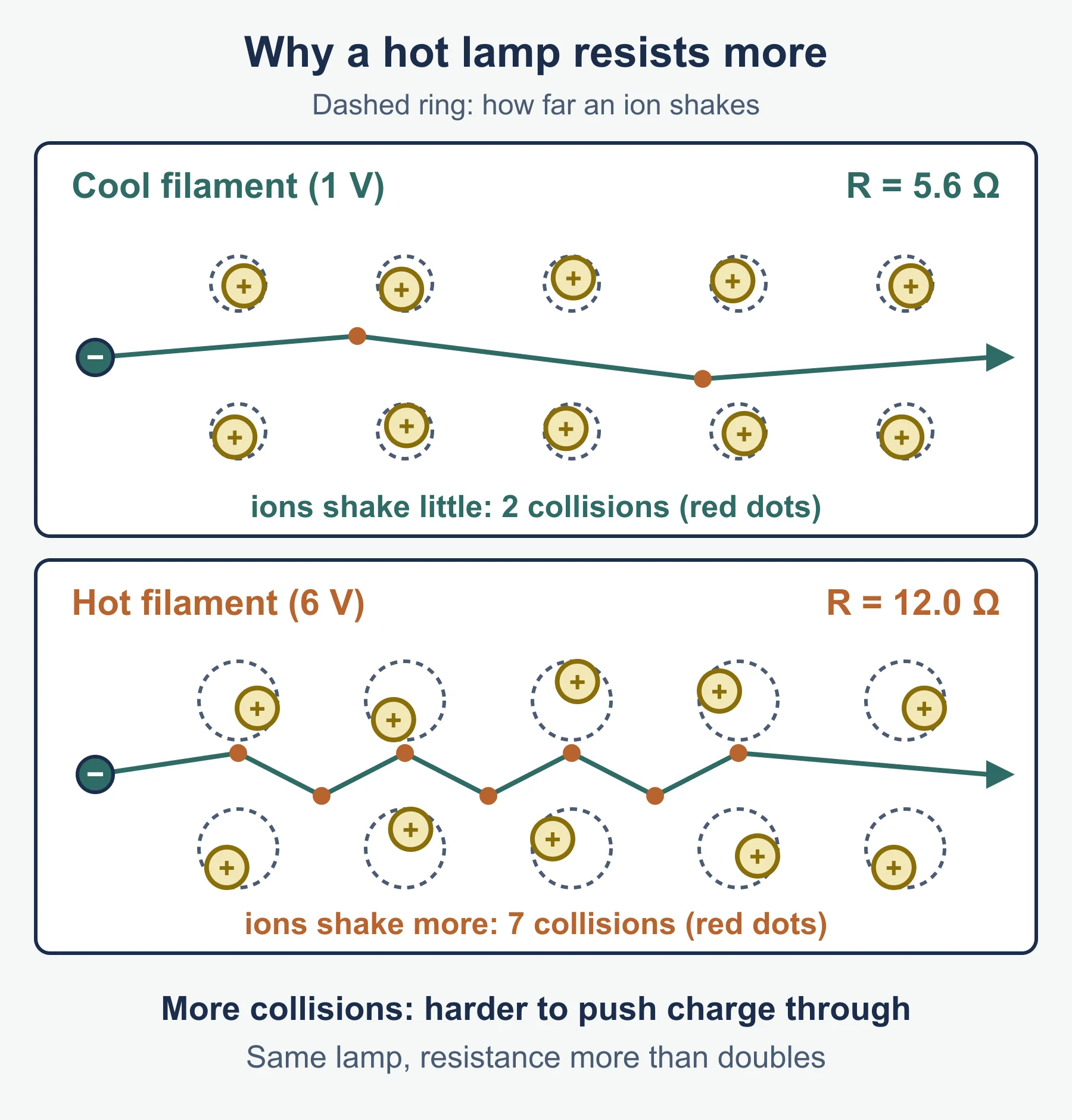
A hotter metal conductor has higher resistance: atoms vibrate more and collide with free electrons more often.
Finding resistance. Circuit with a variable resistor, ammeter in series, voltmeter across the test component. Take several pairs of readings, work out V ÷ I each time, average.
4.3 Circuits
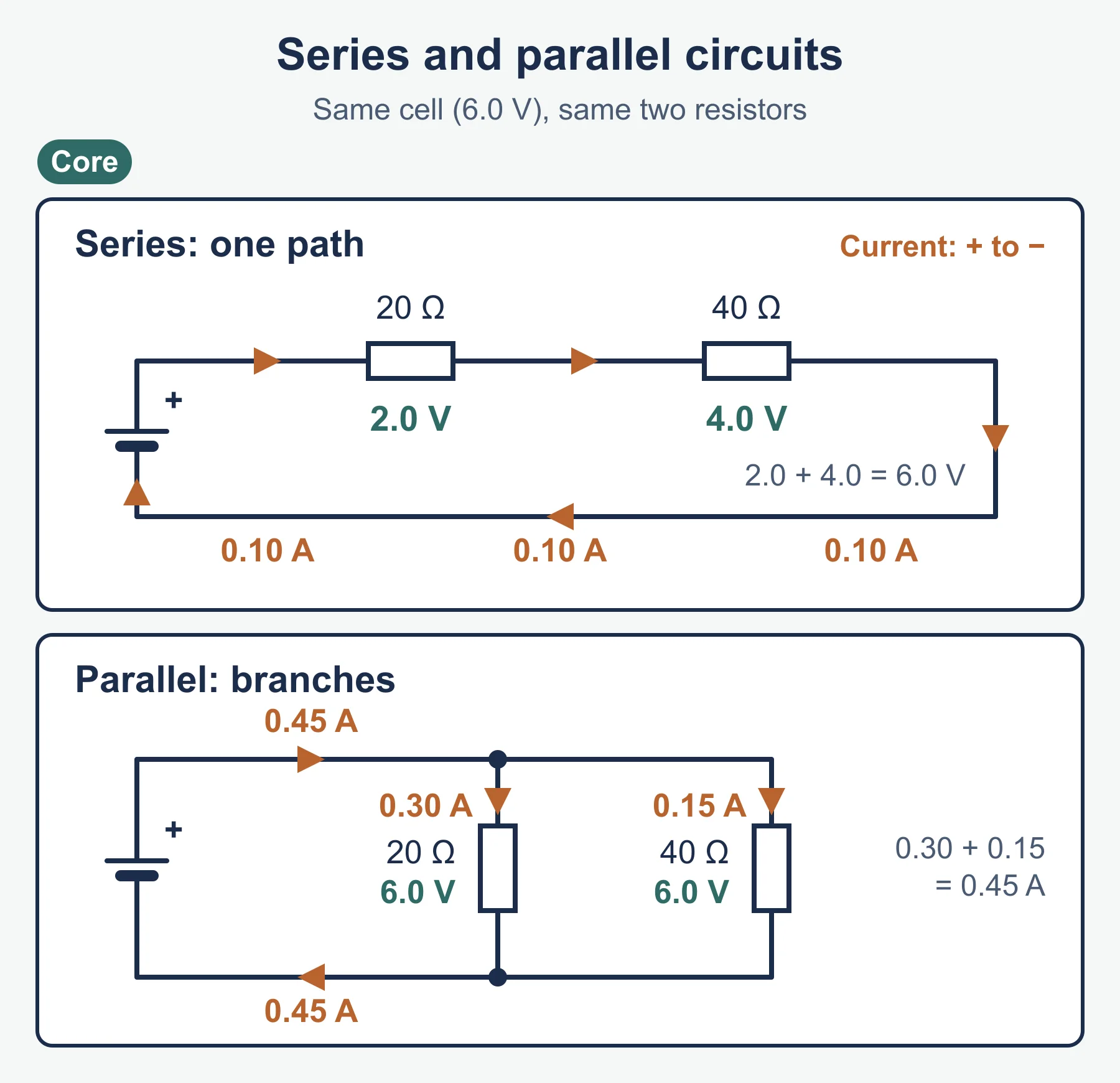
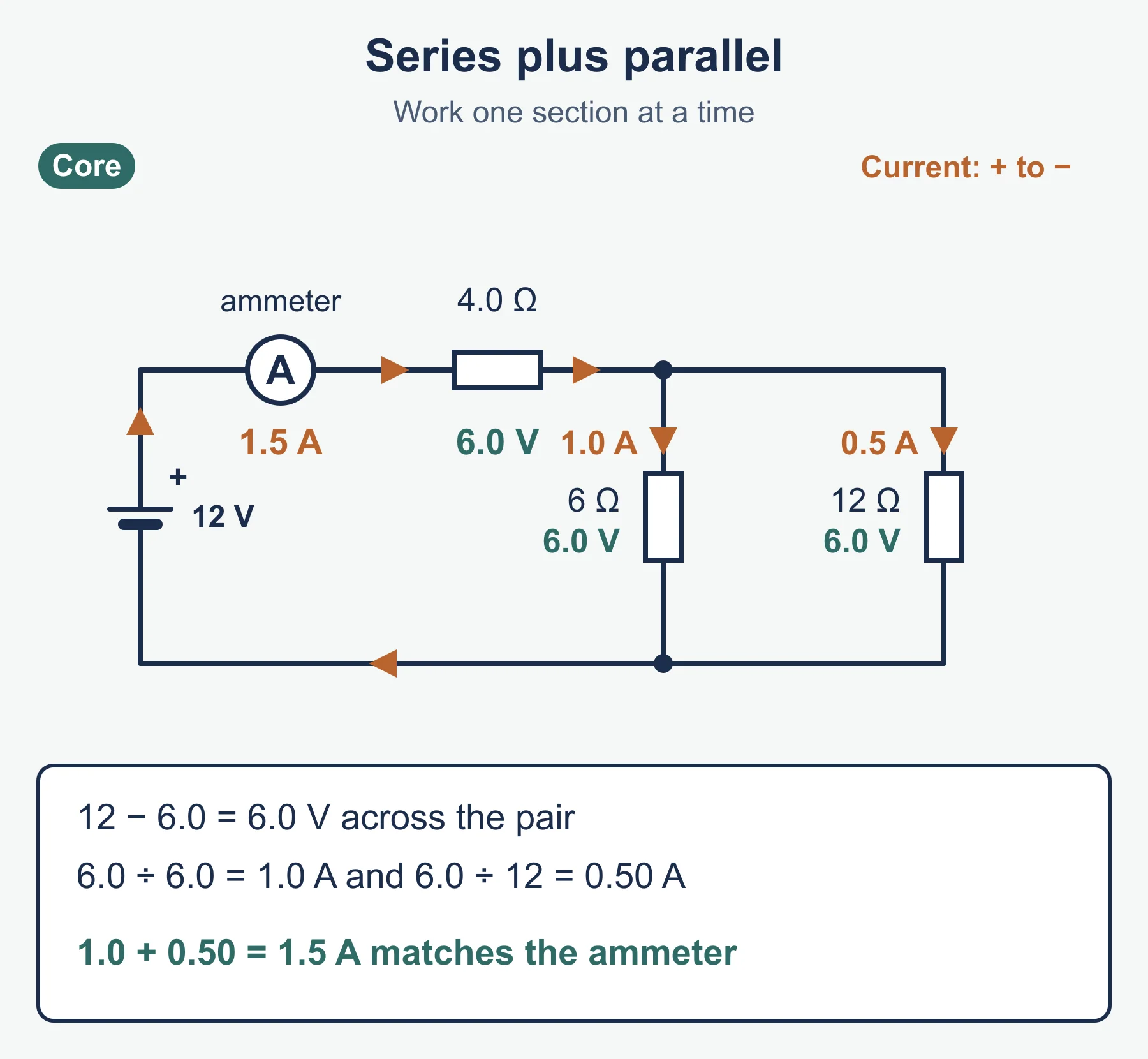
Method in steps: mixed series and parallel
- Combine each parallel pair into one resistance.
- Sum the series resistances for the total.
- Find the supply current: I = V ÷ R.
- Use that current in the series part to find its p.d.
- Take that from the supply p.d. to get the p.d. across the parallel part.
- Divide by each branch resistance to get branch currents, and check they add up.
Components
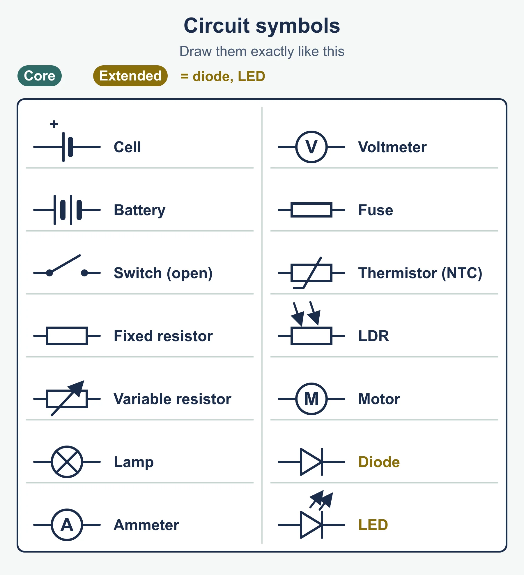
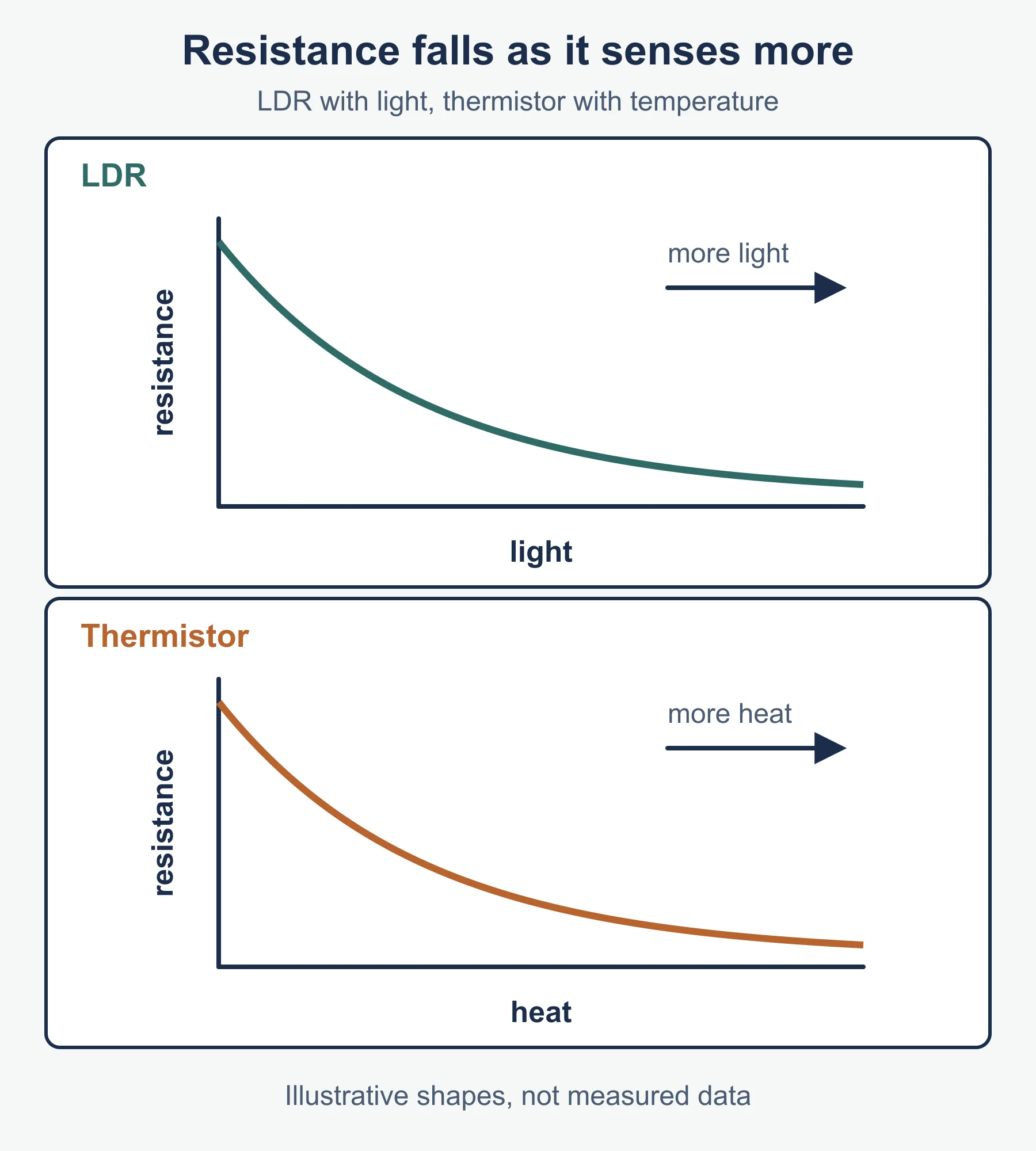
- NTC thermistor: hotter means lower resistance.
- LDR: brighter light means lower resistance.
- Diode: one direction only. LED: a diode that lights up.
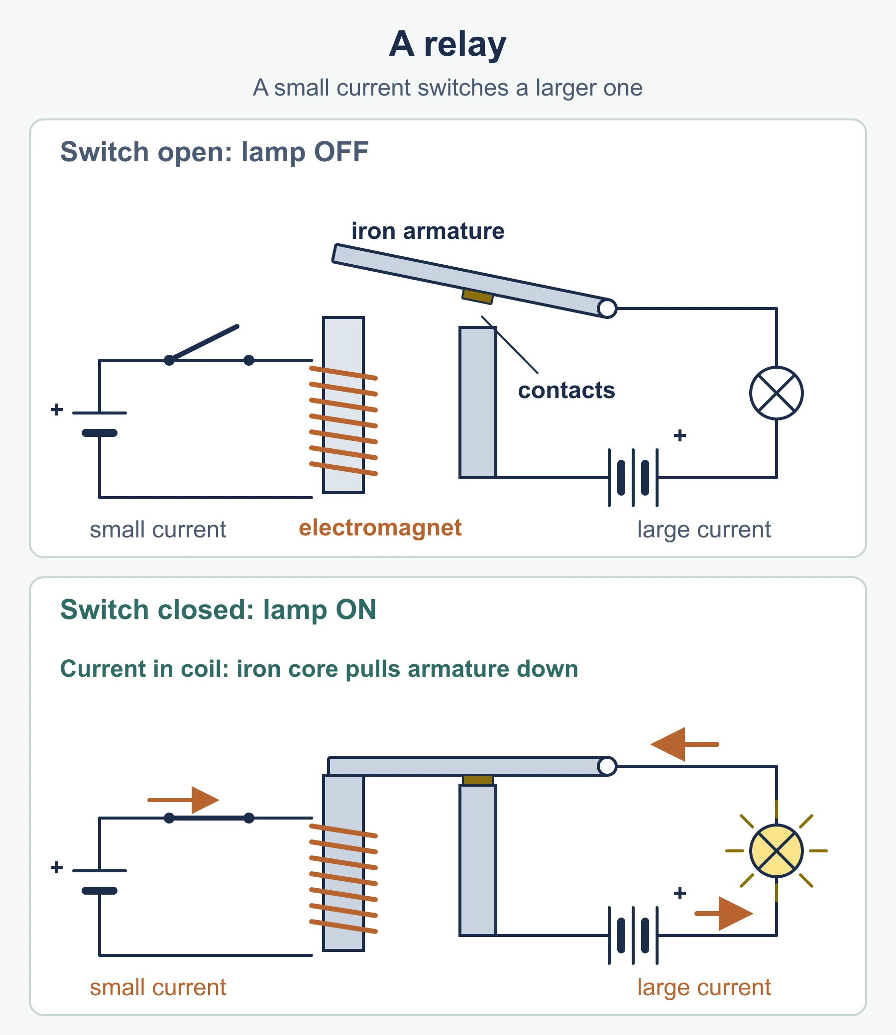
- Relay: a small current in a coil closes a separate switch.
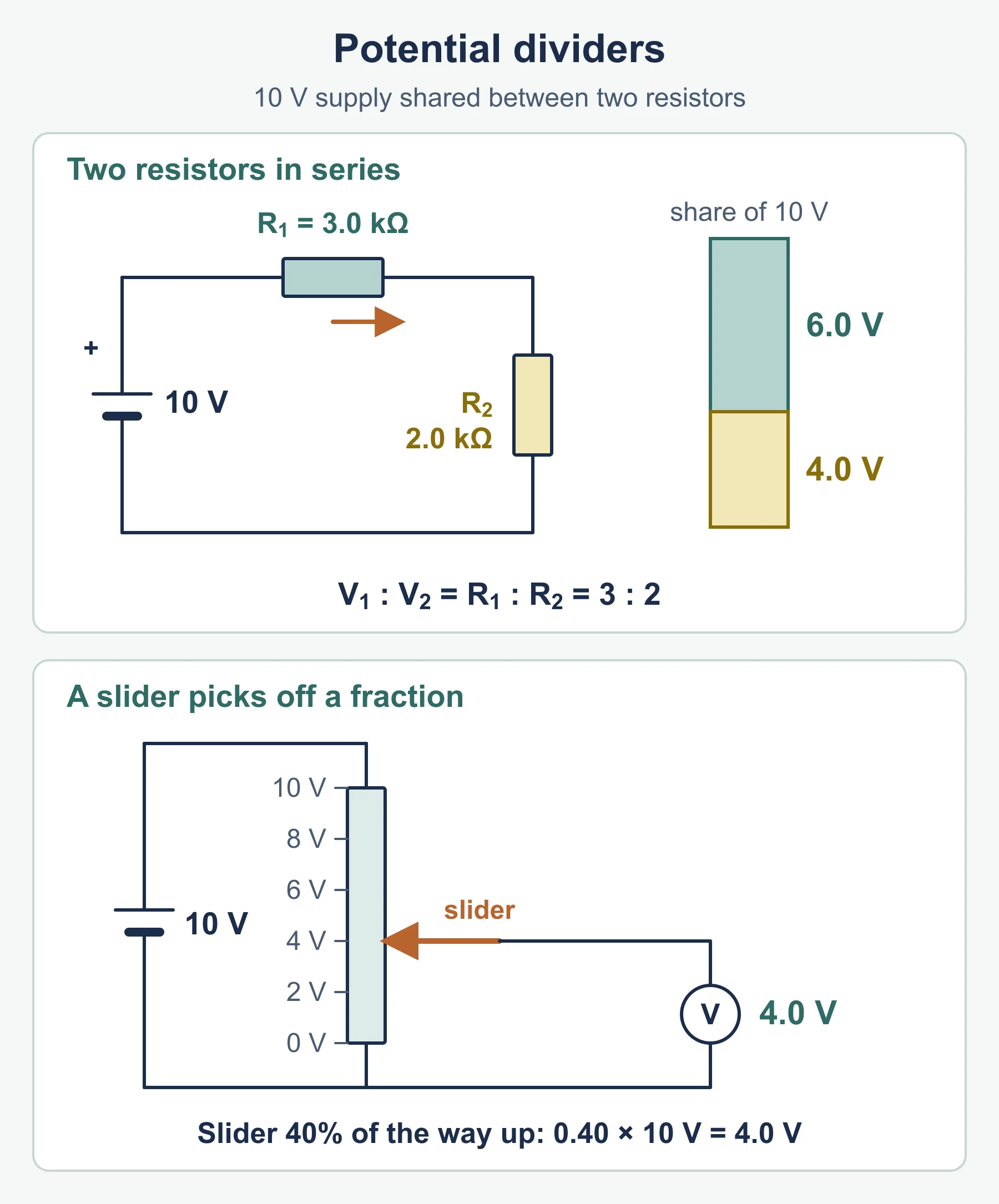
- Variable potential divider: slider takes any fraction of the supply p.d.
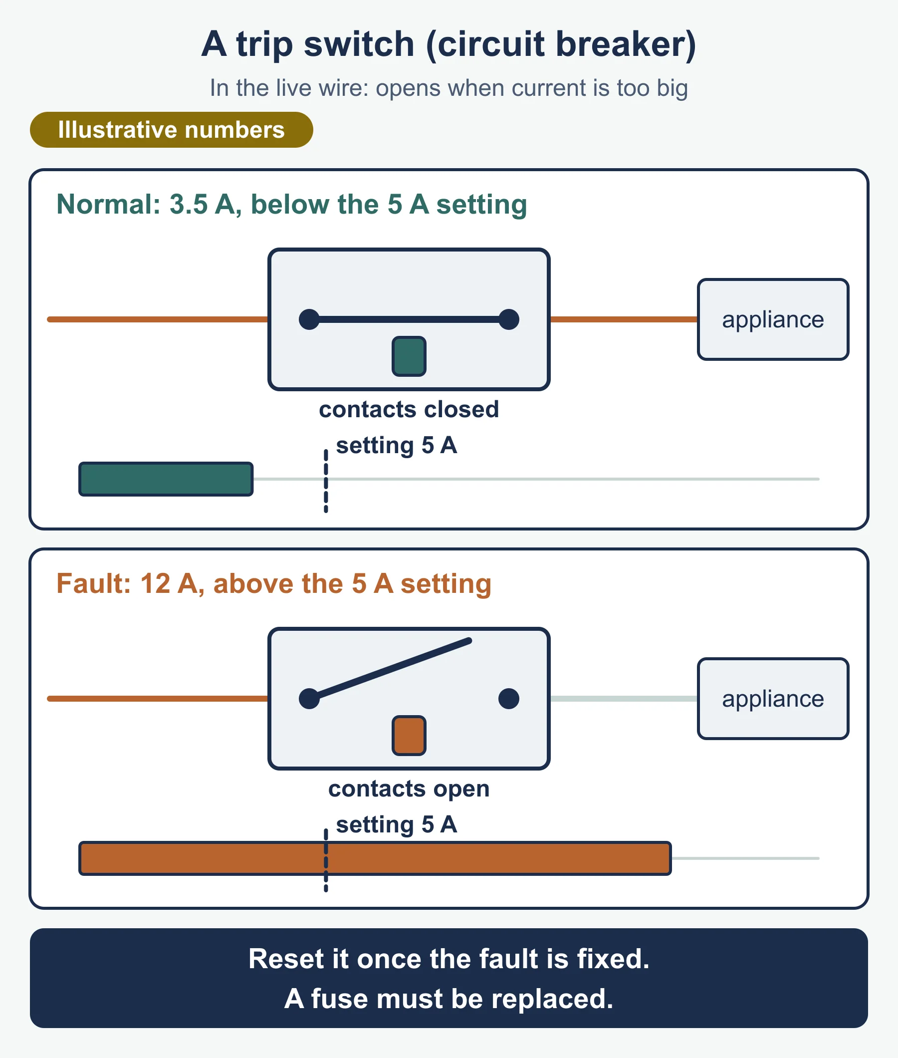
- Fuse: wire melts when the current is too large.
Sensor circuit reasoning
Put the sensor in series with a fixed resistor. Whichever has more resistance gets more of the supply p.d. If a thermistor warms, its resistance falls, its p.d. falls, and the fixed resistor’s p.d. rises. For an LDR, replace “warms” with “light increases”.
4.4 Practical electricity
- Parallel lamps: each has the full supply p.d., works independently, and one failure leaves the rest on.
- 1 kW h = energy transferred when a 1 kW appliance runs for 1 hour.
- Hazards: damaged insulation, overheated cables, damp conditions, overloaded sockets and leads.
- Mains wires: live, neutral, earth.
- Fuse or trip switch: in the live wire, rating just above normal current. A trip switch can be reset.
- Switch: in the live wire, so the appliance is dead when off.
- Earthed metal case: if live touches it, a large current flows to earth, the fuse melts or trip operates and the case is safe.
- Double insulation: non-conducting case, so it cannot become live. A case needs earthing or double insulation.
4.5 Electromagnetic effects
Induction. Moving a magnet and a coil relative to each other induces an e.m.f. No movement, no e.m.f. Bigger with faster cutting of field lines and more turns. Reversing the direction of movement reverses the e.m.f.
Lenz’s law. An induced current acts to oppose the change that causes it.
A.c. generator. Rotating coil in a field, with slip rings and brushes (or a rotating magnet inside a fixed coil). Coil parallel to the field gives the peak or trough; coil perpendicular to the field gives zero. Faster rotation raises the peaks and shortens the period.
Fields from currents. Straight wire: circles, wider spaced further out. Solenoid: bar-magnet pattern. Bigger current: stronger field. Reversed current: reversed field. Right-hand grip rule for direction.
Relay and loudspeaker. Relay: low current operates an electromagnet that switches a high-current circuit. Loudspeaker: varying current in a coil in a permanent magnet’s field moves a cone.
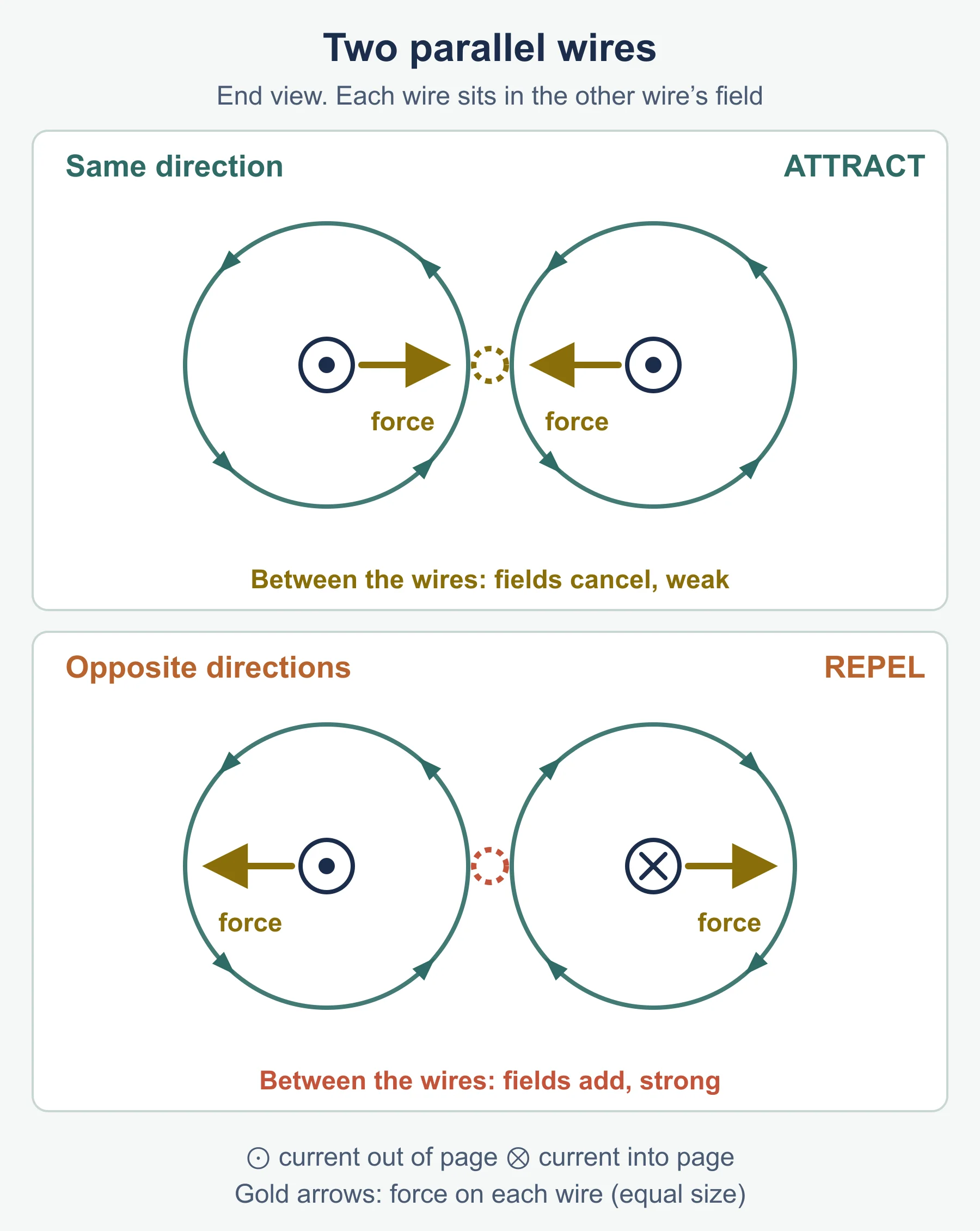
Force on a conductor. If the current or the field is reversed, the force reverses; if both are, nothing changes. Fleming’s left-hand rule: first finger gives field, second finger current, thumb force. Same-direction currents in parallel wires attract; opposite-direction currents repel.
D.c. motor. Turning effect rises with more turns, larger current, stronger field. Split-ring commutator and brushes reverse the coil current every half turn.
Transformer. Two coils on an iron core; a.c. only. Step-up: Ns greater than Np. Step-down: Ns less than Np. High-voltage transmission means lower current for the same power, so less p.d. and less power lost in the cables.
4.6 Oscilloscope
- Shows a waveform as a trace.
- Voltage = vertical divisions × Y-gain.
- Time = horizontal divisions × timebase.
Must-know distinctions
- Charge versus current: charge is in coulombs; current is charge per second.
- Conventional current versus electron flow: opposite directions.
- E.m.f. versus p.d.: the source supplies energy; the component transfers it.
- Series versus parallel: the same current in series; the same p.d. across parallel branches.
- Fuse versus trip switch: both protect; only the trip switch resets.
- Earthing versus double insulation: one gives the fault current a path to ground; the other prevents the case becoming live.
- Generator versus motor: a generator turns motion into an induced e.m.f.; a motor turns a current in a field into motion.
Quick self-test
- A current of 0.60 A passes for 40 s. How much charge is that?
- 540 C passes a point in 30 minutes. What is the current?
- Four identical 1.5 V cells are connected in series, then in parallel. What is the e.m.f. of each arrangement?
- A component has 18 V across it and carries 0.45 A. What is its resistance?
- A 6.0 Ω and a 12 Ω resistor are joined (a) in parallel, (b) in series. Find each combined resistance.
- A transformer has 2300 primary turns on a 230 V supply and 150 secondary turns. What is the secondary p.d., and is it step-up or step-down?
- A 2.4 kW heater runs for 3.0 hours. Electricity costs 15 cents per kW h. How much does this cost?
- A 9.0 V supply is across a 2.0 kΩ and a 4.0 kΩ resistor in series. What is the p.d. across the 2.0 kΩ resistor?
- Wire A has resistance 4.0 Ω. Wire B is the same material but has double the length and double the cross-sectional area. Find the resistance of B.
- An oscilloscope has Y-gain 5.0 V/div and timebase 2.0 ms/div. A trace peaks 1.5 divisions high, and one cycle is 8.0 divisions wide. Find the peak p.d. and the period.
- A lamp takes 0.50 A from a 12 V supply for 60 s. How much energy does it transfer?
- Explain why a fuse is fitted in the live wire and not the neutral wire.
Answers
- Q = It = 0.60 × 40 = 24 C.
- t = 30 × 60 = 1800 s, so I = 540 ÷ 1800 = 0.30 A.
- Series: 4 × 1.5 = 6.0 V. Parallel: 1.5 V.
- R = 18 ÷ 0.45 = 40 Ω.
- (a) (6.0 × 12) ÷ 18 = 4.0 Ω; (b) 6.0 + 12 = 18 Ω.
- Vs = 230 × 150 ÷ 2300 = 15 V, step-down.
- Energy = 2.4 × 3.0 = 7.2 kW h; cost = 7.2 × 15 = 108 cents.
- V = 9.0 × 2.0 ÷ (2.0 + 4.0) = 3.0 V (the other resistor has 6.0 V).
- Double the length doubles R and double the area halves it, so R = 4.0 × 2 ÷ 2 = 4.0 Ω.
- Peak p.d. = 1.5 × 5.0 = 7.5 V; period = 8.0 × 2.0 = 16 ms.
- E = IVt = 0.50 × 12 × 60 = 360 J.
- If the fuse were in the neutral wire, the appliance would still be connected to the live supply after the fuse melted, so touching it could still cause a shock. In the live wire, a blown fuse disconnects the appliance from the live supply.
Where marks are usually lost
- Writing “electricity flows through the fuse” instead of saying the thin wire heats and melts.
- Describing the voltmeter or ammeter connections the wrong way round.
- Leaving out “at constant temperature” when stating Ohm’s law.
- Forgetting to convert minutes to seconds or kilowatts to watts.
- Adding resistances in parallel instead of using the combination equation.
- Saying a thermistor’s resistance “decreases when it is cold”.
- Describing Lenz’s law as “the current opposes” without saying it opposes the change causing it.
- Putting the switch or fuse in the neutral wire.
- Giving an oscilloscope reading in divisions without multiplying by the Y-gain or timebase.
Frequently asked questions
What is a kilowatt-hour? One kilowatt-hour (kW h) is the energy transferred when a 1 kW appliance runs for 1 hour. To find the energy in kW h, multiply the power in kW by the time in hours.
How do you read voltage and time from an oscilloscope trace? Voltage = number of vertical divisions × Y-gain, and time = number of horizontal divisions × timebase. Giving a reading in divisions without multiplying is a common error.
What is the difference between a fuse and a trip switch? Both protect a circuit by cutting off the current when it is too large, and both go in the live wire with a rating just above the normal current. Only a trip switch can be reset.
What must I include when stating Ohm’s law? State that the current in a conductor is directly proportional to the p.d. across it, provided the temperature stays constant. Leaving out the temperature condition is a common way to lose the mark.
Official syllabus
Cambridge O Level Physics 5054 syllabus for 2026, 2027 and 2028, Cambridge International, Section 4: Electricity and magnetism.
Get free revision emails (optional)
Occasional emails with practice questions, worked explanations and links to free resources for the qualification and subjects you choose. No spam, and you can unsubscribe from any email. The free tools on this site never need an email.
Related resources
-
Practice questions
O Level Physics: Uses of an Oscilloscope — Practice Questions (Cambridge 5054)
Original Cambridge O Level Physics 5054 questions with worked answers on oscilloscope traces: Y-gain, timebase, p.d., period, frequency and short time gaps.
Physics · Cambridge · O Level
Try questions -
Study guides
Cambridge O Level Physics: Electricity and magnetism (5054)
A full study guide to Electricity and magnetism for Cambridge O Level Physics 5054: magnetism, circuits, mains safety, induction, motors and transformers.
Physics · Cambridge · O Level
Read guide -
Practice questions
O Level Physics: Electricity and magnetism — Practice Questions (Cambridge 5054)
Original Cambridge O Level Physics 5054 questions with worked answers on measuring resistance, fuses, lighting circuits, trip switches and the d.c. motor.
Physics · Cambridge · O Level
Try questions
Related articles
-
study skills
How to revise for a science examination
Most science revision fails because it rereads notes instead of retrieving them. A practical method for revising physics, chemistry and biology in the weeks before a paper.
14 July 2026
-
teaching
A Level tuition in Dubai: Cambridge or Pearson Edexcel International A Level?
Schools in Dubai and Abu Dhabi teach either Cambridge International AS & A Level or Pearson Edexcel International A Level. How the two are structured, why it matters for tuition, and how online classes from Lahore work.
9 October 2026
Studying this with a teacher
Working through Physics O LEVELS?
This page is free and stays free. If you would rather be taught it, Marlbridge runs Physics classes one-to-one and in small groups of up to 15, online in your own time zone. The first trial class is free. WhatsApp replies within an hour (8am–11pm Pakistan time, every day); email the same day.
Cambridge Physics teachers at Marlbridge